| 1:1 VOLTAGE BALUN |
| 1:1 Ruthroff voltage balun. Install July 2012. |
Construction
The T-200-2 powdered iron toroid core was tightly rapped in a lay of overlapping PVC electrical tape to prevent the enamelled copper wire's insulation being damaged during winding and to offer some additional electrical insulation with core.
The triple bifilar winding of 17 turns are wound evenly spaced around the toroid core with the two individual windings wound close together.
The length of enamelled copper wire per winding for the T-200-2 powdered iron toroid core is determined by length per winder = 50mm per turn plus 200mm tails
The exact number of turns is not critical but the numbers listed in the preceding table should yield good results. It is possible to exceed the power ratings listed above but the performance of the balun may be degraded during high SWR causing heating of the core.

Figure 1 Schematic of the 1:1 Ruthroff voltage balun. Typically unbalanced = 50/75 ohms and balanced = 50/75 ohms.

Figure 2 Wiring of the 1:1 Ruthroff voltage balun.
Table 1 lists alternative toroid core with winding suggestions.
Parts list.
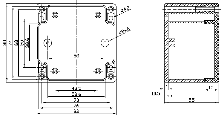
Figure 3 Sealed Polycarbonate Enclosures 82 x 80 x 55mm details
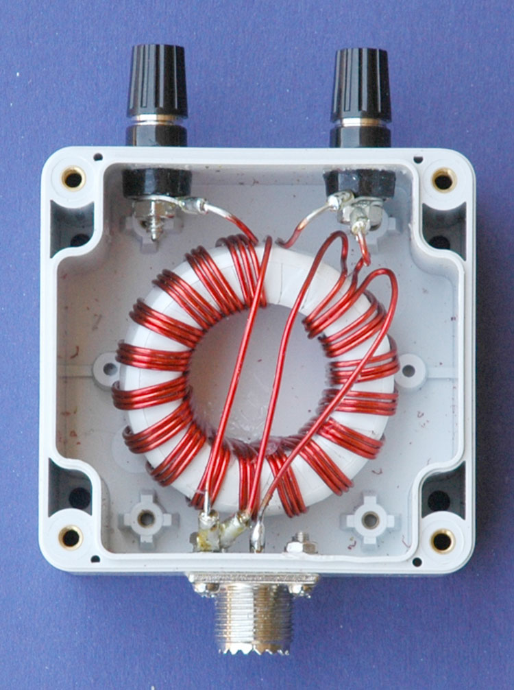
Photo 1 1:1 Ruthroff voltage balun assembled.
The evaluation of the efficiency of the balun over the desired bandwidth (1.8 - 30MHz) was carried out by testing the impedance that could be seen from unbalanced side to a resistive load applied to the balanced side using an antenna analyser. The efficiency is shown to cut of sharply below 1.8MHz and gradually taper of above about 40MHz. The below antenna analyser plot viewing a 100ohm resistive load attached to the balanced side of the balun and measured at a nominal impedance of 50ohms presented as anticipated an approximate 100ohm load to the analyser and produced about a 2:1 SWR. Despite not having carried out this test previously the results are more or less what was expected and demonstrates that the balun's 1:1 voltage transformation occurs efficiently from 1.8 to well above 30MHz
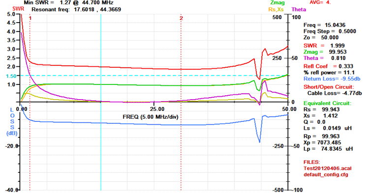
Figure 4 AIM 4170C antenna analyser plot viewing a 100ohm resistive load through the Ruthroff voltage balun. Note the 100ohm resistor appears as 100ohms due to the 1:1 balun ratio resulting in an ideal SWR of 2:1. (1) = 1.8MHz & (2) = 30.MHz.
AIM 4170C antenna analyser explanation;
An additional evaluation of the efficiency of the balun was preformed by simply measuring the RF power at selected frequencies fed into the balun and measuring the out put power from the balun using the set up shown in Figure 7.
For example, RF was applied to the input of the Balun at a frequency of 1.8 MHz at a power of 5 Watts with 4 Watts being measured at the output meter. The below formula was applied revealing a Balun loss of 0.97dB at this frequency.

Figure 5 shows the results of measurements taken at various frequencies including the calculated loss. Figure 6 shows the graphed results of the losses verses frequency.
Concussion of this evaluation is that the efficiency between 3.5 MHz to 14 MHz is very high as to be unnoticeable and that even at 28 MHz the loss would represent only about half an ‘S’ point.
The limitation of this evaluation is that it is under an ideal situation of 50 ohms and that more extreme loads will likely show greater losses.
Figure 5 Table of test results.
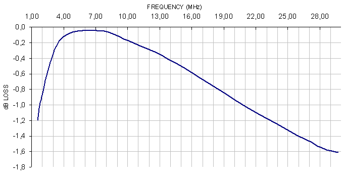
Figure 6 Plot of Balun losses verses frequency.
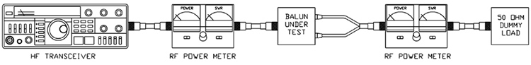
Figure 7 Efficiency evaluation set up.
|
В сети часто встречается схема этого трансформатора с рекомендацией применять феррит с проницаемостью 1000-2000. Можете ли вы подтвердить или опровергнуть эти рекомендации?
ОтветитьУдалитьпроницаемость не критична. Делал балун с проницаемостью ферритового кольца 600, работает отлично.
ОтветитьУдалитьЕсли я правильно понял физику процесса, применяя ВЧ кольцо с малой проницаемостью, мы осуществляем магнитную связь между обмотками через сердечник. Поэтому провода на таком сердечнике свивать не нужно. Если проницаемость высокая,нужна свивка проводов. Делал такой трансформатор на кольце 2000, 10 витков проводом в эмалевой изоляции, намотка параллельными проводами, результат неудовлетворительный... Какое количество витков посоветует сделать на кольце 2000 для 3.6-14 МГц?
ОтветитьУдалитьСколько точно сказать трудно... Но чем ниже частота - тем соответственно больше нужно и витков. 10-12 витков примерно на 7 МГц, на 3,6 я бы поэкспериментировал и взял для начала 15-20.
ОтветитьУдалить