четверг, 26 июня 2014 г.

Обзор посылки из Китая...
это только отчет, который я обещал дать. Как говориться все дошло благополучно, и спасибо огромное Дмитрию Пастухову RN3DHJ за большую поддержку нашего проекта. Все как говориться лучше один раз увидеть, на фотографиях а еще лучше и на видео...


четверг, 19 июня 2014 г.

1:1 VOLTAGE BALUN
1:1 Ruthroff voltage balun. Install July 2012.

Requiring a balun to feed a balanced feed line with an un-balanced T-Match network a 1:1 Ruthroff voltage balun design using aT200-2 Toroid core was selected. While the 4:1 ratio is often referred to for the interface between T-Match network and a balanced antenna system it will often not be the ideal choice when very low impedances are encountered. It is for this reason that I chose to not include the balun as an integral feature of the T-Match network, opting for the flexibility of an outboard balun and the ability to trial various baluns subject to the antenna system and impedances presented.

Construction

The T-200-2 powdered iron toroid core was tightly rapped in a lay of overlapping PVC electrical tape to prevent the enamelled copper wire's insulation being damaged during winding and to offer some additional electrical insulation with core.
The triple bifilar winding of 17 turns are wound evenly spaced around the toroid core with the two individual windings wound close together.

The length of enamelled copper wire per winding for the T-200-2 powdered iron toroid core is determined by length per winder = 50mm per turn plus 200mm tails
The exact number of turns is not critical but the numbers listed in the preceding table should yield good results. It is possible to exceed the power ratings listed above but the performance of the balun may be degraded during high SWR causing heating of the core.

Figure 1  Schematic of the 1:1 Ruthroff voltage balun. Typically unbalanced = 50/75 ohms and balanced = 50/75 ohms.
Figure 1  Schematic of the 1:1 Ruthroff voltage balun. Typically unbalanced = 50/75 ohms and balanced = 50/75 ohms.

Figure 2  Wiring of the 1:1 Ruthroff voltage balun. 
Figure 2  Wiring of the 1:1 Ruthroff voltage balun


TOROIDNUMBER OF TURNSPOWER RATING
T80-2
25
60 Watts
T106-2
16
100 Watts
T130-2
18
150 Watts
T157-2
16
250 Watts
T200-2
17
400 Watts
T200A-2
13
400 Watts
T400-2
14
1000 Watts
Table 1 lists alternative toroid core with winding suggestions.


Parts list.
  • T-200-2 powdered iron toroid core from Amidon
  • About  600mm of 1.25mm Enamelled copper wire.
  • Two black binding posts
  • SO-239 UHF chassis mount connector
  • Sealed Polycarbonate Enclosures 82 x 80 x 55mm from Jaycar. See Fig 3 for details
 Figure 2 Sealed Polycarbonate Enclosures 82 x 80 x 55mm details
Figure 3 Sealed Polycarbonate Enclosures 82 x 80 x 55mm details

Photo 1 1:1 Ruthroff voltage balun assembled. 
Photo 1 1:1 Ruthroff voltage balun assembled. 
The evaluation of the efficiency of the balun over the desired bandwidth (1.8 - 30MHz) was carried out by testing the impedance that could be seen from unbalanced side to a resistive load applied to the balanced side using an antenna analyser. The efficiency is shown to cut of sharply below 1.8MHz and gradually taper of above about 40MHz. The below antenna analyser plot viewing a 100ohm resistive load attached to the balanced side of the balun and measured at a nominal impedance of 50ohms presented as anticipated an approximate 100ohm load to the analyser and produced about a 2:1 SWR. Despite not having carried out this test previously the results are more or less what was expected and demonstrates that the balun's 1:1 voltage transformation occurs efficiently from 1.8 to well above 30MHz   

Figure 3  AIM 4170C antenna analyser plot viewing a 100ohm resistive load through the Ruthroff voltage balun. Note the 100ohm resistor appears as 100ohms due to the 1:1 balun ratio resulting in an ideal SWR of 2:1. (1) = 1.8MHz & (2) = 30.MHz.
Figure 4  AIM 4170C antenna analyser plot viewing a 100ohm resistive load through the Ruthroff voltage balun. Note the 100ohm resistor appears as 100ohms due to the 1:1 balun ratio resulting in an ideal SWR of 2:1. (1) = 1.8MHz & (2) = 30.MHz.
AIM 4170C antenna analyser explanation;
SWRStanding Wave Ratio.
ZmagTotal Impedance.
RsResistive component of the total impedance
XsReactive component of the total impedance also indicating the +/-sign of the value. Inductive being a positive value and capacitive being a negative number.
ThetaPhase angle between voltage and current.
Return LossTotal reflected system loss.

An additional evaluation of the efficiency of the balun was preformed by simply measuring the RF power at selected frequencies fed into the balun and measuring the out put power from the balun using the set up shown in Figure 7.
For example, RF was applied to the input of the Balun at a frequency of 1.8 MHz at a power of 5 Watts with 4 Watts being measured at the output meter. The below formula was applied revealing a Balun loss of 0.97dB at this frequency.  
Figure 5 shows the results of measurements taken at various frequencies including the calculated loss. Figure 6 shows the graphed results of the losses verses frequency.
Concussion of this evaluation is that the efficiency between 3.5 MHz to 14 MHz is very high as to be unnoticeable and that even at 28 MHz the loss would represent only about half an ‘S’ point.
The limitation of this evaluation is that it is under an ideal situation of 50 ohms and that more extreme loads will likely show greater losses.
FrequenciesInput PWROutput PWRdB Loss
1,605,003,80-1,2
1,805,004,00-1,0
3,605,004,80-0,2
7,105,004,950,0
10,105,004,80-0,2
14,505,004,50-0,5
21,105,003,95-1,0
28,105,003,50-1,5
29,705,003,45-1,6
Figure 5 Table of test results.

Figure 6 Plot of Balun losses verses frequency.
Figure 6 Plot of Balun losses verses frequency.

Figure 7 Efficiency evaluation set up. 
Figure 7 Efficiency evaluation set up. 

9:1 VOLTAGE UNUN
9:1  voltage unun.

With the view to establish a quick and easy multi-band antenna deployment for portable and camping operations a simple long wire antenna with an earth or earth plus counterpoise arrangement with a 9:1 voltage unun is one possible solution.
Requiring a unun to feed a long wire antenna ideally without a tuner a  9:1 voltage unun design using a T200-2 Toroid core was selected. 

Figure 1  Typical 9:1 voltage unun and long wire antenna configuration.

Figure 1  Typical 9:1 voltage unun and long wire antenna configuration.


Construction

PVC covered 1mm diameter copper wire was used with the view that the thicker insulation may reduce the possibility of insulation puncture due to the higher nominal impedance.
The triple bifilar winding of 10 turns are wound evenly spaced around the T-200-2 powdered iron toroid core with the three individual windings wound close together. A Green binding posts was selected to clearly identify the common earth connection.

The length of enamelled copper wire per winding for the T-200-2 powdered iron toroid core is determined by length per winding = 50mm per turn plus 250mm tails


Figure 2  Schematic of the 9:1 voltage unun. Typically unbalanced = 50/75 ohms too unbalanced = 450/675 ohms.
Figure 2  Schematic of the 9:1 voltage unun. Typically unbalanced = 50/75 ohms too unbalanced = 450/675 ohms.

Figure 3  Wiring of the 9:1 voltage unun. 
Figure 3  Wiring of the 9:1 voltage unun


TOROIDNUMBER OF TURNSPOWER RATING
T200-2
9
400 Watts

Table 1 Toroid core with winding suggestions.


Parts list.
  • T-200-2 powdered iron toroid core from Amidon
  • About  750mm of 1.0mm Covered copper wire per winding.
  • Black and Green binding posts
  • SO-239 UHF chassis mount connector
  • Sealed Polycarbonate Enclosures 82 x 80 x 55mm from Jaycar. See Fig 4 for details

Figure 4 Sealed Polycarbonate Enclosures 82 x 80 x 55mm details
Photo 1  9:1  voltage unun assembled. 
Photo 1  9:1  voltage unun assembled. 
The evaluation of the efficiency of the unun over the desired bandwidth (1.8 - 30MHz) was carried out by testing the impedance that could be seen from transceiver side unun to a resistive load applied to the antenna side using an antenna analyser. The efficiency is shown to cut of sharply below 5MHz and gradually taper off at about 30MHz. The below antenna analyser plot viewing a 450ohm resistive load attached to the balanced side of the balun and measured at a nominal impedance of 50ohms presented as anticipated an approximate 50ohm load to the analyser and produced about a 1:1 SWR. Despite not having carried out this test previously the results are more or less what was expected and demonstrates that the unun's 1:9 voltage transformation occurs efficiently from 7 to  25MHz. The results are not as satisfying as those carried out on the 1:1 voltage balun showing significant reactance across the band. The results are less than ideal and the application of the design is to be reviewed, but is useful over a limited frequency range from 7MHz to 25MHz,
Figure 3  AIM 4170C antenna analyser plot viewing a 450ohm resistive load through the unun. Note the 450ohm resistor appears as 50ohms due to the 9:1 unun ratio resulting in an ideal SWR of 1:1. 
Figure 5  AIM 4170C antenna analyser plot viewing a 450ohm resistive load through the unun. Note the 450ohm resistor appears as 50ohms due to the 9:1 unun ratio resulting in an ideal SWR of 1:1. 
AIM 4170C antenna analyser explanation;
SWRStanding Wave Ratio.
ZmagTotal Impedance.
RsResistive component of the total impedance
XsReactive component of the total impedance also indicating the +/-sign of the value. Inductive being a positive value and capacitive being a negative number.
ThetaPhase angle between voltage and current.
Return LossTotal reflected system loss.
An additional evaluation of the efficiency of the unun was preformed by simply measuring the RF power at selected frequencies fed into the balun and measuring the out put power from the balun using the set up shown in Figure 8. In this set up it was necessary to have two identical 9:1 ununs, the second to step the impedance back down to the 50 ohms for measuring. It is critically important that the two ununs be made in a identical fashion as the results need to assume that half the losses are as a result of each of the ununs as that the below formula simply halves the resultant overall loss.
For example, RF was applied to the input of the unun at a frequency of 1.8 MHz at a power of 5 Watts with 0.45 Watts being measured at the output meter. The below formula was applied revealing a Balun loss of 5.2dB at this frequency per unun.  

Figure 6 shows the results of measurements taken at various frequencies including the calculated loss. Figure 7 shows the graphed results of the losses verses frequency.
Concussion of this evaluation is that the efficiency between 8.0 MHz to 25 MHz is very low as to be unnoticeable and that even at 25 to 30 Mhz the loss would be almost unnoticeable however the losses are high at 3.5 MHz representing a full 'S' point drop or half the power being lost in the unun. At 1.8 MHz the losses are very high at -5.2 dB, almost 2 'S' points. This unun should be useful from 7.0 MHz to 30 MHz and at push on 3.5MHz if nothing better was avaliable. 
The limitation of this evaluation is that it is under an ideal situation of 50 ohms and that more extreme loads will likely show greater losses.  
FreqInput PWROutput PWRdB Loss
1,605,000,40-5,5
1,805,000,45-5,2
3,605,001,20-3,1
7,105,003,40-0,8
10,105,004,32-0,3
14,505,004,900,0
21,105,004,50-0,2
28,105,003,10-1,0
29,705,002,75-1,3
Figure 6 Table of test results.
          

Figure 7 Plot of Balun losses verses frequency.
          

Figure 8 Efficiency evaluation set up.
              
4:1 VOLTAGE BALUN
4:1 Ruthroff voltage balun. Install July 2012.

Requiring a balun to feed a balanced feed line with an un-balanced T-Match network a 4:1 Ruthroff voltage balun design using aT200-2 Toroid core was selected. While the 4:1 ratio is often referred to for the interface between T-Match network and a balanced antenna system it will often not be the ideal choice when very low impedances are encountered. It is for this reason that I chose to not include the balun as an integral feature of the T-Match network, opting for the flexibility of an outboard balun and the ability to trial various baluns subject to the antenna system and impedances presented.

Construction

The T-200-2 powdered iron Toroid core was tightly rapped in a lay of overlapping PVC electrical tape to prevent the enamelled copper wire's insulation being damaged during winding and to offer some additional electrical insulation with core.
The double bifilar winding of 17 turns are wound evenly spaced around the toroid core with the two individual windings wound close together.

The length of enamelled copper wire per winding for the T-200-2 powdered iron toroid core is determined by length per winder = 50mm per turn plus 200mm tails
The exact number of turns is not critical but the numbers listed in the preceding table should yield good results. It is possible to exceed the power ratings listed above but the performance of the balun may be degraded during high SWR causing heating of the core.  

Figure 1  Schematic of the 4:1 Ruthroff voltage balun. Typically unbalanced = 50/75 ohms and balanced = 200/300 ohms.
Figure 1  Schematic of the 4:1 Ruthroff voltage balun. Typically unbalanced = 50/75 ohms and balanced = 200/300 ohms.

Figure 2  Wiring of the 4:1 Ruthroff voltage balun. 
Figure 2  Wiring of the 4:1 Ruthroff voltage balun


TOROIDNUMBER OF TURNSPOWER RATING
T80-2
25
60 Watts
T106-2
16
100 Watts
T130-2
18
150 Watts
T157-2
16
250 Watts
T200-2
17
400 Watts
T200A-2
13
400 Watts
T400-2
14
1000 Watts

Table 1 lists alternative toroid core with winding suggestions.


Parts list.
  • T-200-2 powdered iron toroid core from Amidon
  • About  600mm of 1.25mm Enamelled copper wire.
  • Two black binding posts
  • SO-239 UHF chassis mount connector
  • Sealed Polycarbonate Enclosures 82 x 80 x 55mm from Jaycar. See Fig 3 for details
Figure 3 Sealed Polycarbonate Enclosures 82 x 80 x 55mm details

Photo 1 4:1 Ruthroff voltage balun assembled. 
Photo 1 4:1 Ruthroff voltage balun assembled. 
The evaluation of the efficiency of the balun over the desired bandwidth (1.8 - 30MHz) was carried out by testing the impedance that could be seen from unbalanced side to a resistive load applied to the balanced side using an antenna analyser. The efficiency is shown to cut of sharply below 1.8MHz and gradually taper of above about 30MHz. The below antenna analyser plot viewing a 100ohm resistive load attached to the balanced side of the balun and measured at a nominal impedance of 50ohms presented as anticipated an approximate 25ohm load to the analyser and produced about a 2:1 SWR. Despite not having carried out this test previously the results are more or less what was expected and demonstrates that the balun's 1:4 voltage transformation occurs efficiently from 1.8 to  30MHz. The results are not as satisfying as those carried out on the 1:1 voltage balun showing significant reactance across the band. Despite the less than ideal analyser plot the balun appears to work well as an interface between the T-Match tuner and the balanced multi-band antenna system.
Figure 2  AIM 4170C antenna analyser plot viewing a 100ohm resistive load through the Ruthroff voltage balun. Note the 100ohm resistor appears as 25ohms due to the 4:1 balun ratio resulting in an ideal SWR of 2:1. (1) = 1.8MHz & (2) = 30.MHz.
Figure 4  AIM 4170C antenna analyser plot viewing a 100ohm resistive load through the Ruthroff voltage balun. Note the 100ohm resistor appears as 25ohms due to the 4:1 balun ratio resulting in an ideal SWR of 2:1. (1) = 1.8MHz & (2) = 30.MHz.
AIM 4170C antenna analyser explanation;
SWRStanding Wave Ratio.
ZmagTotal Impedance.
RsResistive component of the total impedance
XsReactive component of the total impedance also indicating the +/-sign of the value. Inductive being a positive value and capacitive being a negative number.
ThetaPhase angle between voltage and current.
Return LossTotal reflected system loss.
  
An additional evaluation of the efficiency of the balun was preformed by simply measuring the RF power at selected frequencies fed into the balun and measuring the out put power from the balun using the set up shown in Figure 7. In this set up it was necessary to have two identical 4:1 baluns, the second to step the impedance back down to the 50 ohms for measuring. It is critically important that the two baluns be made in a identical fashion as the results need to assume that half the losses are as a result of each of the baluns as that the below formula simply halves the resultant overall loss.
For example, RF was applied to the input of the Balun at a frequency of 1.8 MHz at a power of 5 Watts with 1.95 Watts being measured at the output meter. The below formula was applied revealing a Balun loss of 2.0dB at this frequency per bulun.

Figure 5 shows the results of measurements taken at various frequencies including the calculated loss. Figure 6 shows the graphed results of the losses verses frequency.
Concussion of this evaluation is that the efficiency between 3.0 MHz to 30 MHz is very low as to be unnoticeable and that even at 1.8 Mhz the loss would represent less than an ‘S’ point being almost unnoticeable.
The limitation of this evaluation is that it is under an ideal situation of 50 ohms and that more extreme loads will likely show greater losses.
FreqInput PWROutput PWRdB Loss
1,605,001,80-2,2
1,805,001,95-2,0
3,605,003,60-0,7
7,105,004,58-0,2
10,105,004,900,0
14,505,005,000,0
21,105,004,900,0
25,005,004,60-0,2
29,705,003,90-0,5
Figure 5 Table of test results.  
            

Figure 6 Plot of Balun losses verses frequency.  
     

Figure 7 Efficiency evaluation set up.


четверг, 5 июня 2014 г.

How to connect to ScoutLink

IRC

There are different ways you can connect to ScoutLink. If you already have an IRC-Client or you want to install one then just enter the data provided, and connect. If you do not know how to install an IRC-Client or how to enter the data just look at our configure mIRC page.
If you think that all is to complicated then just start with one of our webchats.
Here is the info you need for your IRC-Client
Networkname: ScoutLink
Port: 6667
Server: chat.scoutlink.net
Here is an example how it could look on mIRC.
There are a lot of servers, please choose one near to your location. The following list shows you the names of servers near to you. Using one of them always connects you to a server in your region. If you do not know what to choose just take chat.scoutlink.net. Port is always 6667

chat.scoutlink.netConnects you to a random server
chat.eu.scoutlink.netUse this if you are somewhere in Europe
chat.nl.scoutlink.netUse this if you are from The Netherlands
chat.de.scoutlink.netUse this if you are from Germany
We also offer IPv6 enabled Servers, please use chat.ipv6.scoutlink.net to connect to them.

Secure IRC (IRC-SSL)

All of our servers have SSL enabled. Using SSL encrypts your connection to the server, so that no one between you and the server could read the data you are sending. Our port for secure IRC is 6697.  All Servers support ssl.
You have to tell your client that it trusts the SSL certificate, you also have to tell the client that it should use SSL. See the "configure client" section for more details. For mIRC you have to enter the port as "+6697".

TeamSpeak

ScoutLink is more than just text based chatting via IRC. We also offer a TeamSpeak Server and we hope to include other services in the future.
Information on how to setup your TeamSpeak client, so that you can talk to others, can be found at our TeamSpeak page.

среда, 28 мая 2014 г.

Вышел третий номер журнала радиоскаут http://scoutdx.ucoz.ru/load/0-0-0-7-20 вы можете узнать как работает первая в России скаутская коллективная радиостанция R6LCA. 

четверг, 22 мая 2014 г.

LPD  в руках радиолюбителя
Всем известно что безлицензионные LPD радиостанции работают в участке любительского диапазона, а любительские радиостанции могут работать на частотах LPD. Что из этой ситуации, может использовать радиолюбитель?
1. Получается так, если оператор работает на частоте 433500кГц с мощностью 5Вт и называет выданный ему радиолюбительский позывной, он является радиолюбителем, подчиняется 'Инструкции о порядке регистрации и эксплуатации любительских радиостанций'.

2. Если же оператор на 18 канале (433500кГц) уменьшит мощность до 10мВт и перестанет называть свой любительский позывной, он выпадает из радиолюбительского регламента, может говорить о чём угодно, с кем угодно, придумать себе позывной и тд.

При использовании LPD радиостанций, у радиолюбителя появляются дополнительные преимущества и незначительные недостатки, по сравнению с обычной любительской радиостанцией:

  • Не нужно бегать с бумажками по инстанциям.
    Все радиолюбители знают с какими препятствиями приходится сталкиваться при регистрации и получении разрешения на носимую (возимую) радиостанцию. С LPD таких проблем нет, поставил автомобильную антенну и работай из машины. Положил в карман и иди с ней куда хочешь.

  • Купил и работай
    Купить LPD радио можно дешево и совершенно свободно, не нужно ничего регистрировать, никуда ходить и платить. При этом сохраняется возможность легально общаться с радиолюбителями в пределах 433-434Мгц.
  • Ограничения
    Появляется несколько ограничений связанных с конструкцией LPD радио (вместо частоты номер канала, мощность 10мВт, всего 69 частот, нет разноса частот).
  • Стоимость и доступность
    LPD станции имеют низкую стоимость (от 1000руб за 1шт.) и продаются в большом кол-ве магазинов. В тоже время радиолюбительские станции YAESU и ICOM стоят значительно дороже, купить их сложнее. При этом разница в технических характеристиках минимальна!
  • Функциональность
    Конечно ICOM и YAESU имеют больше наворотов, в LPD есть только то что действительно нужно для радиосвязи, это сканирование, двойной приём, VOX, экономайзер, изменение мощности передатчика, иногда вибровызов, CTCSS, громкость, шумодав и другие стандартные функции.
  • Мощность передатчика
    Возможно цифра 10мВт (QRPP) вас смутит, но её достаточно чтобы работать на несколько километров. При необходимости, есть возможность увеличить мощность до 1-3Вт. На различных форумах описано как это сделать.
  • Антенны
    Никто не мешает использовать направленные, стационарные автомобильные антенны с LPD радиостанциями и таким образом повысить дальность связи в несколько раз. Некоторые модели не имеют антенного разьёма, но для радиолюбителя это не проблема.
  • Характеристики
    Основные технические характеристики LPD радиостанций (чувствительность, экономичность, внеполосные излучения и тд.) не уступают ICOM, YAESU. Таким образом, LPD радио можно рассматривать как дешевую альтернативу радиолюбительской носимой радиостанции.
  • Питание
    LPD станции как правило используют 3-4 дешевые батарейки АА или ААА, что значительно удобнее чем дорогой фирменный аккумулятор.
  • Общение
    LPD позволяют общаться не только с радиолюбителями, но и с туристами, альпинистами, лыжниками, отдыхающими и другой публикой на курортах нашей страны. Можно послушать местное такси, охрану магазинов и строителей. Только не нужно вклиниваться в их разговоры и мешать! Будьте вежливы и благоразумны.


  • Тюнинг LPD радиостанций
    Станции этого типа выпускает много фирм, неплохо себя зарекомендовали MOTOROLы, ICOMы, но они дорогие. Из дешевых это ALAN/MIDLAND, они широко распространены, их легко доделать, поднастроить, модифицировать. На них есть схемы и описания. Если у радиолюбителя есть желание улучшить работу своей LPD радиостанции, необходимо:

  • проверить чувствительность приёмника
  • мощность передатчика
  • резонанс антенны
  • уровень девиации
  • порог шумоподавителя
  • точность установки частот в синтезаторе
  • поискать в internet рекомендации по конкретной модели
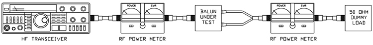
    После проверки и подстройки радиостанции MIDLAND G-225, включая небольшие модернизации описанные на lpd.radioscanner.ru получились следующие характеристики:
  • ток потребления в режиме дежурного приёма (без экономайзера, шумодав закрыт) 37мА
  • всё как и в предыдущем примере, только включена подсветка 50мА
  • с включенным экономайзером (без подсветки) 16мА
  • при максимальной громкости (шипение эфира) 100мА
  • передача на большой мощности HI 520мА (после переделки)
  • передача на маленькой мощности LO 350мА (после переделки)
  • девиация передатчика ±4кГц.
  • чувствительность моего экземпляра около 0.18мкв
  • мощность передатчика в режиме HI (нагрузка 50ом) 1.4Вт
  • АЧХ приёмника видна на картинке ниже
  • LPD в руках у радиолюбителя
    АЧХ не идеальна, желательно увеличить завал в области высоких частот и это можно сделать, но учитывая цену радиостанции с этой особенностью можно мириться. Теперь сравним некоторые характеристики моего экземпляра G-225 с современными радиолюбительскими УКВ станциями:
    модельJRX без экономайзераJTX при макс. мощностимощность TXчувствит. RXразмерывес
    VX-3R60ма1.1-1.3A1-1.5Вт0.16мКв47х81х23мм130гр
    IC-E7 (IC-P7A)80ма1.3-1.5A1.5Вт0.18мКв47х81х28мм160гр
    TH-F6A95-170ма1.7-2.0A4Вт0.18мКв58х87х30мм250гр
    G-22537ма520мА1.4Вт0.18мКв60х100х35мм100гр

    Отсюда можно сделать вывод - многие характеристики LPD радиостанции G-225 находятся на уровне современных радиостанций. Если сломается YAESU или ICOM, рвут волосы на ж...пе, а если ломается G-225 её выкидывают и покупают новую. Чтобы разобраться в возможностях VX-3, человеку с высшим образованием нужно прочитать инструкцию минимум пару раз. В G-225 всё просто и логично, инструкция нужна только для дебилов.
    Характеристики потребления от аккумуляторов приведены для того чтобы понять простую вещь, при одинаковом количестве переговоров, G-225 будет работать в 2-3 раза дольше чем ICOM IC-E7. Это важно, при использовании радиостанций вдали от источников энергии.
    У VX-3 например есть КВ приёмник, диапазон 145Мгц, тренжёр CW и другие нужные и не нужные навороты. Однако вспомним, что в первую очередь это радиостанция и покупают её РАДИОСВЯЗИ! Вот по этому параметру YAESU VX-3 за 7000руб равноценна MIDLAND G-225 за 1000руб! Дальность связи и качество модуляции у этих радиостанций на частоте 434500кГц (18 канал), примерно одинаковые.
    Вернёмся к тюнингу:
    1. Первым делом проверяем соответствие частоты, для этого берём частотомер или приёмник имеющий возможность работать в SSB на 430мгц, например FT-857D. Устанавливаем точно частоту (по нулевым биениям), аккуратно поворачивая подстроечный конденсатор CT201. В моём экземпляре G-225 несовпадение частоты составляло -900Гц. Вроде бы для ЧМ и немного, но лучше подстроить.
    2. Исправим врождённый дефект G-225 который заключается в отсутствии земли на диодной сборке. На фотографии видно, в каком месте нужно сделать перемычку. Улучшается экономичность передатчика.
    3. Увеличиваем уровень девиации, для этого крутим по часовой стрелке подстроечный резистор RV2. Оптимальная девиация для LPD около ±4кГц. Если сделать больше или меньше, то при слабом сигнале ваша речь будет менее разборчива.
    4. Уменьшаем порог открытия шумоподавителя. Для этого крутим RV1 против часовой стрелки, до того момента когда станция зашипит, потом возвращаемся назад на 2-3 градуса и оставляем так. В городе, многочисленные помехи от ПК, кабельных сетей и тд. устраняются включением CTCSS.
    5. В целом к модуляции претензий нет, но мне захотелось чуть поднять высокие частоты, для этого меняем конденсатор С52 (0.1мкф) на 5100-9600пф. и снова настраиваем уровень девиации, так как она немного упадёт. Можно поступить по другому и скорректировать цепи обратной связи в микрофонном усилителе. Третий вариант, тупо подобрать другой микрофон и впаять вместо родного.
    Описанная настройка заняла примерно 20 минут. Сравнение G-225 c лежащей рядом VX-3, показало что слабые сигналы станции принимают одинаково (на слух). Дальность связи на внешнюю автомобильную антенну ANLY 144/430, также одинаковая.
    Типовая дальность связи между двумя однотипными LPD радиостанциями, при мощности передатчика 10мВт, составляет примерно 2км на открытом пространстве (в поле), до 800м в редком лесу, до 400 метров в плотной застройке (город) или густом лесу. В горах, при условии прямой видимости, дальность может вырасти до 5 - 10км.

    LPD в руках у радиолюбителя

    Рекомендации
    Антенна у G-225 имеет длину всего 50мм, это значит что КПД её очень низкий, что уменьшает дальность связи. Исправить это можно двумя путями, первый заключается в установке полноразмерной (165мм) антенны вместо спирали. Второй, это поставить SMA разьём и уже к нему прикручивать любые другие антенны.
    Чтобы во время путешествий с радиостанцией, не возникало лишних вопросов со стороны 'органов' (хотя это редкий случай), распечатайте и наклеите на аккумуляторную крышку маленькую памятку. Это напоминание о номере постановления правительства РФ, по которому вы имеете право носить радиостанцию с собой.
    Автомобильная модификация G-225 заключается в установке разьёма (вместо антенны) для подключения к нему внешней автомобильной антенны на магните, внешнего динамика и стабилизатора (подключенного к прикуривателю) на 5-6В с током 1А. В таком варианте, дальность связи увеличивается как минимум в двое.
    Туристическая модификация для многодневных походов, включает полноразмерную антенну (165мм) и небольшую солнечную батарею, для зарядки аккумуляторов радиостанции и другой аппаратуры (фотоаппарат, кпк, телефон).
    При питании от батареек, мощность передатчика больше чем при питании от аккумуляторов!
    Радиостанцию нужно беречь от влаги и мороза! Если она лежала под дождём или упала в воду, нужно её выключить, разобрать и высушить. Делается это элементарно, путём откручивания четырёх винтов. Зимой вам придётся прятать станцию под одежду, так как полежав на морозе, она перестанет работать.
    G-225 оказалась пригодна обмена цифровой информацией в режиме PACKET RADIO (разьёмы есть на корпусе) и отлично работала на скорости 300-600-1200бод. с TNC-2 без каких либо дополнительных модификаций. CTCSS должен быть отключен. Параметр TXDELAY выбираем от 50-70 и более.

    Заключение
    Характеристики некоторых дешевых LPD радиостанций соответствуют аналогичным дорогим моделям других фирм. Радиолюбители всех категорий, могут с успехом их использовать для QRPP соревнований, во время слётов, для организации локальных 'круглых столов' и тд, работая в разрешенном участке диапазона 430МГц (433.075 - 434.775МГц).
    В этой статье для примера взята радиостанция G-225, но это не значит что она лучшая, есть много других достойных моделей (например MIDLAND, АРГУТ, ICOM и тд). Просто G-225 оказалась под рукой во время написания статьи.
    Вызывная частота для радиолюбителей в LPD, это 18 канал без подтона или (в случае помех) с CTCSS 8. На радиолюбительском языке это будет частота 433500кГц, CTCSS 88.5Гц.
     

    http://radon.doolru.org.ua